100 Years of Cigweld – A Brief History of the Brand

100 Years of CIGWELD

CIGWELD is an iconic Australian brand embedded in Australian history (CIG, MUREX, EMF, JB ARNOLD, COMOX, Australian Oxygen and Industrial Gases) and has been part of the welding industry for 100 Years (Est. 1922).

The journey of CIGWELD began in Australia on June 1st 1922 in Melbourne as JB Arnold; a manufacturing company specialising in gas welding and spray-painting equipment where the well-known COMET Branded Gas Welding and Cutting Torches was created. In 1935, JB Arnold then became a part of the Commonwealth Industrial Gases (CIG).

In 1923 E.M.F. Electric (Electro Magnetic Force) was founded to manufacture welding transformer machines. In 1937 EMF became the electric welding division of what would become CIG. CIG finally had a complete portfolio of both gas and electrical welding equipment. EMF also then started to manufacture Covered Welding electrodes for Stick Welding, known official as Manual Metal Arc Welding (MMAW).

Sixty-three years later in 1985, CIGWELD was formed as the equipment division of CIG which was the largest Australian manufactured of Welding Machines, Gas Equipment, Filler Metals and Safety products. At the time CIGWELD employed 700 employees in Australia with another 120 located in the Philippines.

From 1989, there were various transfers of the business (the Management Team (Comweld Group Pty Ltd) who brought CIGWELD from CIG, sold the business to Thermadyne Corporation USA, which later changed its name to Victor Technologies) and more recently in 2014 was bought by our current parent company ESAB-Colfax, now called ESAB Corporation, based in the USA.

From the advent of Oxy-Acetylene Welding (OAW), Manual Metal Arc Welding (MMAW), commonly known as STICK Welding to the invention of TIG welding and MIG welding, CIGWELD has actively brought these welding technologies to Australia, NZ and the Pacific Islands throughout its 100 year history.

With 100 years of industry leading experience, CIGWELD is looking to the future, to continue its leadership in the supply of the highest-level quality products and services to the next generation welders and fabricators, who will weld in the centuries to come.

CIGWELD Customers; share our past, are our present and will determine our future!

How to Choose a Welding Gas Regulator in Australia

How to Choose a Welding Gas Regulator in Australia Matter

Selecting the right regulator starts with choosing one that is designed for your specific gas and provides the pressure or flow needed for the job. All gas regulators sold in Australia should be designed in accordance with AS 4267, with each gas type featuring a unique cylinder connection to prevent incorrect regulator-to-cylinder fitment. This guide explains how to select the correct regulator for oxygen, acetylene, LPG, argon, and CO₂, outlines safe installation practices, and identifies when regulator replacement is required.

Selecting the right regulator starts with choosing one that is designed for your specific gas and provides the pressure or flow needed for the job. All gas regulators sold in Australia should be designed in accordance with AS 4267, with each gas type featuring a unique cylinder connection to prevent incorrect regulator-to-cylinder fitment. This guide explains how to select the correct regulator for oxygen, acetylene, LPG, argon, and CO₂, outlines safe installation practices, and identifies when regulator replacement is required.

What a Gas Regulator does

A regulator performs two critical functions. They reduce the high pressure stored in the cylinder (often up to 20,000 kPa for oxygen, argon, and other inert gases) to a safe working pressure, whilst maintaining consistent pressure as the cylinder contents are used.

They also maintain consistent outlet pressure, which distinguishes a true regulator from a simple flow restriction device. This consistency helps keep cutting flames stable and shielding gas coverage uniform, from a full cylinder through to near empty.

Gas Regulator Selection Table

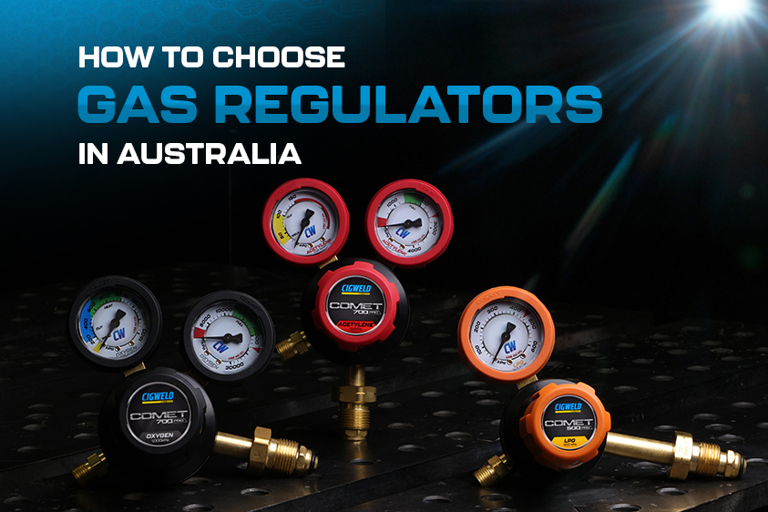
Start by identifying the gas, as each regulator is designed for a specific gas type. The table below shows the compatible applications for each COMET gas regulator. “VI” refers to a vertical inlet regulator and “SI” refers to a side inlet regulator, with the choice depending on how the regulator is mounted to the cylinder.

GasSuited ApplicationCOMET Regulator Part NumberMax outletCylinder inlet
OxygenOxy-fuel cutting, heating, brazingCOMET 700 Oxygen, VI (301637) or SI (310638); 400 kPa VI (310639)1,000 kPa (400 kPa on 310639)Oxygen
AcetyleneGas welding, cutting, heatingCOMET 700 Acetylene, VI (301532)150 kPaType 20
LPGOxy-LPG cutting, heating, brazingCOMET 500 LPG, SI (301525)400 kPaLPG
ArgonMIG and TIG shielding gasCOMET 500 Argon, VI (310601); Argon Preset (310602)45 L/min; 200 kPa PresetType 10
CO2MIG shielding gasCOMET 500 CO2, SI (310795)20 L/minType 30

The COMET 700 series also includes a Nitrogen (310801), Inert (310802) and Hydrogen (310803) regulator for purging and specialty work.

As a rule of thumb, the 700 PRO range suits demanding workshop and site environments, while the 500 PRO range covers everyday industrial applications.

Why Do Gas Threads and Colors Differ?

Each gas is supplied with a unique cylinder connection, ensuring that regulators can only be fitted to the gas they are designed to control. For example, acetylene and hydrogen cylinders use a left-hand (Type 20) thread, while CO₂ cylinders use a dedicated Type 30 connection. COMET regulators are also colour-coded by gas type, making it easy to identify the correct regulator.

The safety rule is straightforward: only use a regulator with the gas it is specifically designed for. If a regulator does not fit the cylinder connection, do not force it or use an adaptor. Always verify that the regulator label matches the cylinder contents before making a connection.

Pressure vs Flow: Understanding Shielding Gas Regulators

Oxygen and fuel regulators are typically adjusted by outlet pressure, measured in kPa, as torch tips and cutting nozzles are designed to operate at specific pressures. Shielding gas applications such as MIG and TIG welding work differently, as weld protection depends on gas flow rate rather than pressure. For this reason, COMET argon and CO₂ regulators are flow-rated, displaying output in litres per minute (L/min) to allow accurate flow control.

The COMET Argon Preset regulator (310602) provides a fixed outlet pressure of 200 kPa and is suited to systems where flow is controlled downstream using a separate flowmeter. For applications requiring flow adjustment directly at the cylinder, the flow-rated COMET 500 Argon regulator (310601) is the preferred option.

When using CO₂, additional safety precautions are required. As CO₂ can displace oxygen and create an asphyxiation hazard in confined spaces, regulators should only be installed and operated in well-ventilated areas. It is also important to note that the pressure relief valve fitted to a CO₂ regulator is designed to protect the regulator itself and should not be relied upon as a safety device for downstream equipment.

Common Regulator Applications in Australian Workshops

  • Farm and rural maintenance. Oxy-fuel equipment is commonly used for cutting steel, heating seized components, and straightening damaged parts in locations where electrical power may not be readily available. These applications typically require an oxygen regulator matched with either an acetylene or LPG regulator.
  • Fabrication and repair workshops. Cutting, heating, straightening, and gas welding operations depend on correctly matched oxygen and acetylene regulators to ensure safe and consistent performance.
  • MIG and TIG welding stations. Argon and CO₂ regulators are used to control shielding gas delivery, helping maintain weld quality by providing consistent gas flow and protecting the weld pool from contamination.
  • Mobile service vehicles. On-site cutting, brazing, and heating applications demand durable regulators capable of withstanding transport and harsh working conditions. COMET regulators feature rubber gauge guards to help protect gauges from accidental impacts.

When selecting a fuel gas, it is important to consider the intended application. LPG is well suited to cutting, heating, and brazing, while acetylene is required for oxy-fuel gas welding applications.

COMET Regulator Start-Up and Shutdown Procedures

This sequence follows the COMET operating manual. Read the full manual and your workplace safety procedures before you start.

  1. Remove the cylinder valve dust seal and crack the valve open briefly to clear dust. Point the outlet away from people and ignition sources and crack fuel gas valves only in a well-ventilated area.
  2. Check that the regulator label and the cylinder marking match. Tighten the inlet connection firmly with a suitable spanner, but not excessively.
  3. Connect the outlet hose. For oxy-fuel work, fit at least an AS 4603 flashback arrestor and non-return valve on each gas line. AS 4839 recommends fitting them at both the regulator and the torch.
  4. Wind the adjusting knob right out, stand to one side of the regulator and open the cylinder valve slowly. A sudden surge can damage the internal parts.
  5. With the downstream valves closed, turn the knob clockwise to roughly your working pressure, then check every connection for leaks with leak detection solution or soapy water. Never use a flame.
  6. Purge each line by opening one downstream valve at a time for several seconds (longer on long hoses), then close it before opening the next. Never purge oxidizing or flammable gases near a flame, lit cigarette or other ignition source.
  7. Open the torch or equipment valve and fine-tune the knob until the outlet gauge shows the pressure you need. The gauge only shows true working pressure with downstream valves open, so finish the setting with gas flowing.

When you finish, close the cylinder valve, open the downstream valves to drain the lines in a well-ventilated area away from ignition sources, then wind the adjusting knob out and close the valves again.

Three rules from the manual are worth repeating. Keep oil, grease and anything combustible away from oxygen regulators and fittings. Never use acetylene at a pressure above 150 kPa. And never use a regulator that isn’t made for oxygen in oxygen service.

If you’re starting from scratch, a kit saves you matching the parts yourself. The COMET Gas Kits pair COMET 700 regulators (plus a COMET 500 LPG regulator in the oxy-LPG kits) with a cutting torch or blowpipe set, flashback arrestors for the torch and regulator ends, fitted twin hose, nozzles or tips, goggles and a lighter, all in a hard case, and conform to AS 4839.

When to Service or Replace a Regulator

  • Five-year limit. The COMET manual says regulators, flashback arrestors, blowpipes, attachments, mixers and cutting torches must be refurbished or replaced after five years of service, as noted in AS 4839-2001.
  • Damage or contamination. Don’t use a regulator with broken, missing, worn, distorted or contaminated parts. Replace those parts, or the regulator, straight away.
  • Flashback arrestors. Have them inspected and tested by a competent person every 12 months, and have them inspected after any flashback.
  • Spare parts. Gauges, gauge guards, seat capsule assemblies, diaphragms and O-rings are listed in the COMET manual for the 700 and 500 ranges.
  • Warranty. CIGWELD covers gas regulators for 5 years, with shorter periods for seat assemblies and gauges (6 months) and elastomer seals and O-rings (3 months). Check the full terms in the manual.

COMET Regulator Features

COMET regulators conform to AS 4267. Across the range, internal gas control components are protected against flashback, and the gauges are designed to fail safe so no parts are thrown if a regulator fails. The 700 series adds a fully encapsulated Tri-Port seat with an integrated sintered filter, and rubber gauge guards for impact protection. Each unit is color coded by gas and laser engraved for identification and traceability.

Backed by 100+ years of CIGWELD expertise, the full range is on the COMET regulators page.

Frequently Asked Questions

Can I use an oxygen regulator on an acetylene cylinder?

No. Each gas has its own cylinder connection, and acetylene uses a left-hand thread, so the regulator won’t fit. The COMET manual says never to connect a regulator designed for one gas to a cylinder holding any other gas, and never to use a non-oxygen regulator in oxygen service.

What pressure should I set my acetylene regulator to?

Never above 150 kPa, which is also the maximum outlet of the COMET 700 acetylene regulator. Within that limit, set the pressure to suit your torch and tip using the tip manufacturer’s chart.

Do I need flashback arrestors on my regulators?

Yes, for oxy-fuel work. The COMET manual requires at least an AS 4603 flashback arrestor and non-return valve on each gas line, and AS 4839 says that for optimum protection they should be fitted at both the regulator and the torch. Have them inspected and tested by a competent person every 12 months.

How long does a gas regulator last?

The COMET manual says regulators must be refurbished or replaced after five years of service, as noted in AS 4839-2001. Replace one sooner if it is damaged, leaking or has contaminated parts.

Can I use an argon regulator for CO2?

No. Argon and CO2 have different cylinder connections (Type 10 and Type 30), and CO2 regulators are fitted with a pressure relief valve to protect the regulator. For CO2, use the COMET 500 CO2 regulator (310795).

What is the difference between the COMET 700 and COMET 500?

Both conform to AS 4267 and protect internal gas control components against flashback. The 700 PRO is built for demanding environments and has a fully encapsulated Tri-Port seat with a sintered filter. The 500 PRO covers everyday industrial applications. The 700 range covers oxygen, acetylene, nitrogen, inert and hydrogen, while the 500 range covers argon, LPG and CO2.

This guide is general information. Always follow the operating manual for your equipment and your workplace safety procedures.

Silicon Carbide (SiC) Inverter Welding Machines Explained: Benefits, Performance & Why They Matter

Silicon Carbide (SiC) Inverter Welding Machines Explained: Benefits, Performance & Why They Matter

In this article

Silicon carbide has become one of the more common terms on welder spec sheets over the past few years, usually printed next to the price tag as if it settles the argument on its own. It’s a fair thing to be sceptical about. Plenty of terms get used in marketing without much behind them.

Silicon carbide isn’t one of those. It’s a genuine improvement in how an inverter welder is built, and it has a real, measurable effect on how the machine performs. It just doesn’t matter equally to everyone, and it’s worth understanding what it does before deciding whether it’s worth paying extra for.

What silicon carbide actually is

Silicon carbide is a compound of silicon and carbon, and it’s not new. It’s one of the hardest synthetic materials available and has been used in grinding wheels and sandpaper for well over a century. Anyone who’s ground back a weld with a flap disc has almost certainly handled it without realising.

What’s changed more recently is the ability to grow silicon carbide into the pure crystal form needed for semiconductors and transistors, the small components that do the actual work inside an inverter power supply. Engineers found that silicon carbide made a noticeably better semiconductor material than plain silicon, which is what nearly every inverter welder has used since inverters replaced transformer machines decades ago.

That’s the essence of it: the same job, done with a better material. The rest of this comes down to why that swap makes a practical difference.

Where it sits inside the machine

Every inverter welder works on the same basic principle. It takes AC power from the wall, converts it to DC, then switches that DC on and off tens of thousands of times a second. That switched output then passes through a transformer, which steps it down to the low-voltage/high-current power an arc actually needs, before it’s sent out to the torch. The component doing the switching is a transistor, and how fast it can switch affects more than just itself: the faster the switching frequency, the smaller and lighter the transformer can be while doing the same job. That’s part of why SiC machines can end up more compact overall, not purely because the transistor runs cooler, but because everything downstream of it can shrink too.

In a conventional inverter, that switching is done by a silicon IGBT (Insulated Gate Bipolar Transistor). In a SiC inverter, it’s done by a silicon carbide MOSFET instead. The transformer, wire feed system, control board, and torch are still built on the same principles either way, but a machine genuinely engineered around SiC will typically pair the faster switch with a smaller transformer and lighter cooling to make the most of it. The transistor is what makes the improvement possible, but it’s the rest of the design working with it that actually delivers it in practice, a point worth keeping in mind, and one this article comes back to a little further down.

SiC vs the standard silicon inverter

 Regular inverter (silicon IGBT)SiC inverter (silicon carbide MOSFET)
Switching speedLimited by a residual current lag as the switch turns offFaster, without that lag
Heat generatedHigherLower
Operating temperatureRuns hotter under sustained loadStays cooler at the same output
Thermal ceiling before performance dropsLowerHigher
Size and weightBulky, with heavy and larger heatsinks for coolingSmaller with lighter cooling systems
Performance over long, high-amperage runsTends to fall awayHolds up more consistently

The underlying reason is a matter of material physics rather than manufacturing preference. In a silicon IGBT, a portion of the current lingers for a fraction of a second after the switch turns off, an effect engineers call tail current, and it’s what limits how quickly a silicon IGBT can switch and wastes energy as heat on every cycle.

That raises a reasonable question: ordinary MOSFETs don’t suffer from tail current the way IGBTs do, so why didn’t welding manufacturers just use plain silicon MOSFETs from the start? The answer comes down to current handling. A plain silicon MOSFET struggles to carry the higher currents a welding inverter needs without a real efficiency penalty, so despite the tail current drawback, silicon IGBTs became the standard choice for high-power inverters simply because they could handle that current better than a silicon MOSFET could.

Silicon carbide removes that trade-off rather than shifting it somewhere else. A SiC MOSFET switches the same clean way an ordinary MOSFET does, with no tail current, while still handling the higher voltage and current a welding inverter needs, which is exactly what plain silicon MOSFETs were never quite able to do at this scale. On top of that, silicon carbide can withstand a much higher electric field in a much smaller volume than silicon, and conducts heat away considerably more effectively. The result is a switch that’s fast, clean, and cooler, without giving up any current-handling capability to get there.

What it means for the person holding the torch

For all the changes inside the machine, they’re only useful if they translate into something noticeable at the work bench; and they do!

A steadier arc is one of the more immediate differences, particularly at lower amperage. Faster switching lets the machine respond to changes in the arc almost instantly, which shows up as a cleaner, more consistent bead, especially on thinner materials where an unstable arc becomes obvious quickly.

A better duty cycle follows on from that. Because the switching component isn’t wasting as much energy as heat, the machine’s internals stay cooler for longer under load, meaning less time spent waiting for it to cool before continuing.

That same reduction in heat also means manufacturers can build smaller, lighter machines without compromising on power. A large part of the bulk in a conventional inverter exists purely to manage heat; larger heatsinks and cooling fans. Since SiC semiconductors generate less heat to begin with, that hardware can shrink without the output shrinking with it, which matters for anyone regularly moving a machine between sites.

There’s a modest efficiency saving too. Less energy lost as heat means more of the power drawn from the wall actually goes into the weld, which adds up over time for a machine used daily in a fabrication setting.

And because silicon carbide tolerates higher operating temperatures before performance starts to drop off, machines built on it are less likely to throttle back on a genuinely hot day in a shed with no airflow, a fairly common Australian summer scenario for anyone welding outside an air-conditioned workshop.

When you’ll notice it, and when you won’t

For light or occasional welding, weekend projects, small home repairs, a well-built silicon inverter will do the job perfectly well, and the difference may not be noticeable at all. Silicon carbide earns its keep in a narrower set of circumstances:

  • Extended, high-output work such as structural fabrication, where a conventional inverter would ordinarily need to pause and cool.
  • Precision work on thin or heat-sensitive material, including aluminium panels, sheet metal, and thin-gauge stainless, where arc stability at lower amperage has a direct effect on weld quality.
  • Site work, where generator power, ambient heat, and machine reliability all carry more weight than they do in a controlled workshop environment.

The catch

Silicon carbide components remain more expensive to manufacture than plain silicon, and that cost is generally reflected in the price of the machine, though the gap has narrowed considerably as SiC production has scaled up across the industry. It’s also worth noting that the presence of silicon carbide alone doesn’t guarantee a better machine. The rest of the design needs to be built around it to realise the full benefit; simply substituting the component without adjusting the surrounding engineering delivers a smaller improvement than the specification sheet might suggest. It’s a detail worth judging machine by machine rather than assuming from the label.

Is it worth paying for?

For anyone welding professionally, running long sessions, working at higher amperage, or moving equipment between job sites regularly, the efficiency and heat advantages of silicon carbide tend to justify the additional cost fairly quickly. For lighter or occasional use, a well-constructed traditional inverter will still perform reliably, and the premium may not be necessary yet. As with most welding equipment decisions, the technology inside the machine matters less than the overall build quality and the warranty backing it.

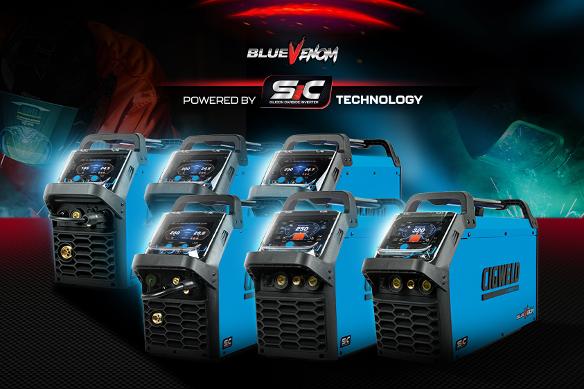
CIGWELD’s own BlueVenom SiC range is built around this exact technology, engineered specifically to take advantage of the faster switching and lower heat generation silicon carbide offers rather than simply swapping the component in. For anyone weighing up whether the step up is worth it for their own work, it’s a practical starting point to see the specs and duty cycle figures side by side against a conventional inverter.

FAQs

What does silicon carbide actually do in a welder?

It’s used to build the switching component inside the power supply, replacing the conventional silicon IGBT with a faster, cooler-running silicon carbide MOSFET. That change is what improves efficiency, arc stability, and duty cycle.

Is a silicon carbide welder genuinely better, or mostly marketing?

It’s a genuine improvement for sustained or high-output welding, delivering better efficiency, duty cycle, and arc stability. For light or occasional use, the difference compared with a good standard inverter is unlikely to be noticeable.

Why do silicon carbide welders cost more?

The components themselves are more expensive to manufacture, although prices have come down as more manufacturers adopt the technology. Over time, the cost is often offset through lower running costs, and reduced downtime.

Why is a faster switching speed better?

Faster switching lets the machine make finer, more frequent adjustments to the arc rather than broader, slower corrections, which is what produces a steadier arc and a cleaner bead. It also allows smaller transformers and other passive components to do the same job, since higher-frequency electronics can be physically smaller without losing performance, part of why faster-switching machines can end up lighter and more compact too.

Do I need a silicon carbide welder for home or hobby use?

Not generally. A solid standard inverter is well suited to occasional repairs or hobby projects. Silicon carbide becomes more relevant once welding is frequent, sustained, or done at higher amperage.

Does silicon carbide genuinely improve duty cycle?

Yes. Because it wastes significantly less energy as heat than a standard silicon IGBT, the internal components take longer to reach their thermal limit, allowing for longer welding sessions before the machine needs to cool.

Want to see one in person? Find your nearest CIGWELD stockist →

Store Locator

Find your nearest CIGWELD ESAB distributor or service agent.. Search by postcode or suburb to locate trusted partners who stock our products and support our full range of welding solutions.